Examining Targeted Attacks
Targeted attacks are generally divided into two categories:
1. Targeting a Specific Organization or Company
This type of targeted attack focuses on a specific organization, with the attacker aiming to gain access to confidential information, such as business documents. A notable example of this is the Aurora attack.
2. Targeting Specific Software or Technological Infrastructure
Unlike the first category, this type of attack is not directed at a specific organization but rather at the data of specific software. For instance, banking applications or SCADA systems are common targets. These attacks are usually highly flexible and, notably, have a greater potential for damage compared to the first category. This is because the attacker can infiltrate more than one organization. These attacks are often long-term in nature, requiring careful planning to bypass security systems and achieve their objectives. Stuxnet is a prime example of such an attack.
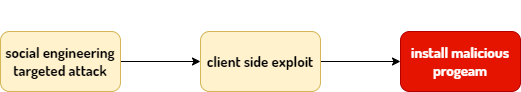
Common Vectors for External Targeted Attacks
The most common vector for external targeted attacks is exploiting vulnerabilities in popular client-side applications, such as web browsers. Typically, attackers achieve their goals after progressing through several phases to gain access to their targets.
One of the main and critical objectives of malware in targeted attacks is the ability to bypass security mechanisms. It is worth noting that one of the business sectors of cybercriminals is the sale of tools that assist malware in staying hidden from security mechanisms, such as antivirus software.
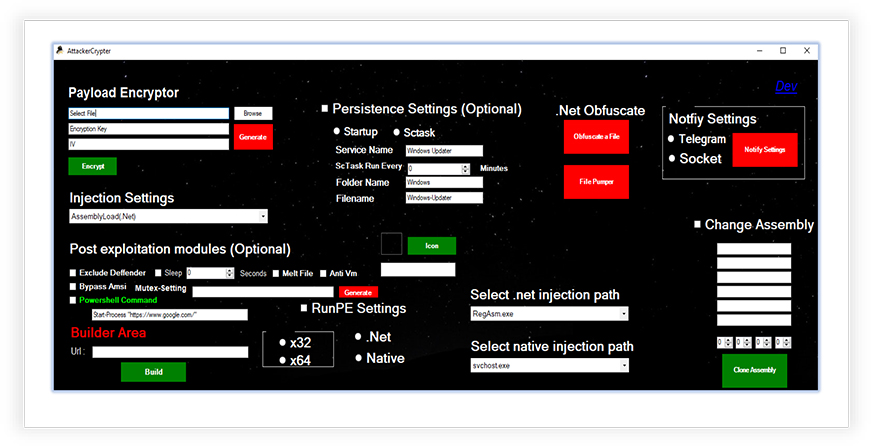
The use of this approach extends the lifespan of older malware and increases the period during which they remain undetected by security products. It is important to note, however, that malware does not always employ these technologies; in some cases, instead of using techniques to bypass security products like antivirus software, they try to make their actions appear as legitimate programs (Stuxnet also utilized this approach).
The Stuxnet attack raised doubts about the trustworthiness of programs that had legitimate digital signatures, and it also made it easier for security products that followed whitelisting mechanisms to be bypassed. This is because, by default, security products did not scrutinize files with valid digital signatures and trusted them. As previously mentioned, instead of using specific techniques to bypass security products, Stuxnet attempted to present itself as legitimate software, achieving this by using a valid digital signature from a trusted company.
Moreover, Stuxnet exploited a zero-day vulnerability that was executed automatically, enabling it to spread across target systems. All of these factors indicate a targeted, long-term attack.
Stuxnet Worm Spread Statistics
The image below shows the global spread statistics of the Stuxnet worm from the time it was identified until September of the same year.
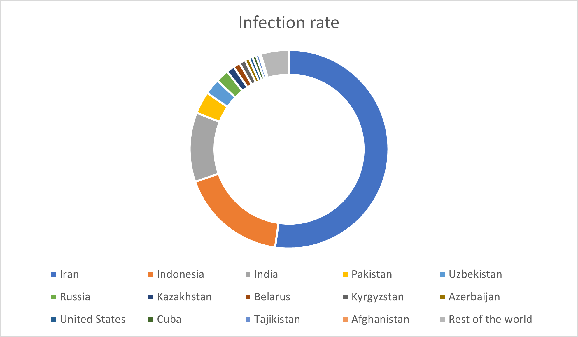
As seen, Asian countries have the highest infection rates, with Iran showing the most significant spread of Stuxnet. The image below illustrates the infection levels in other countries.
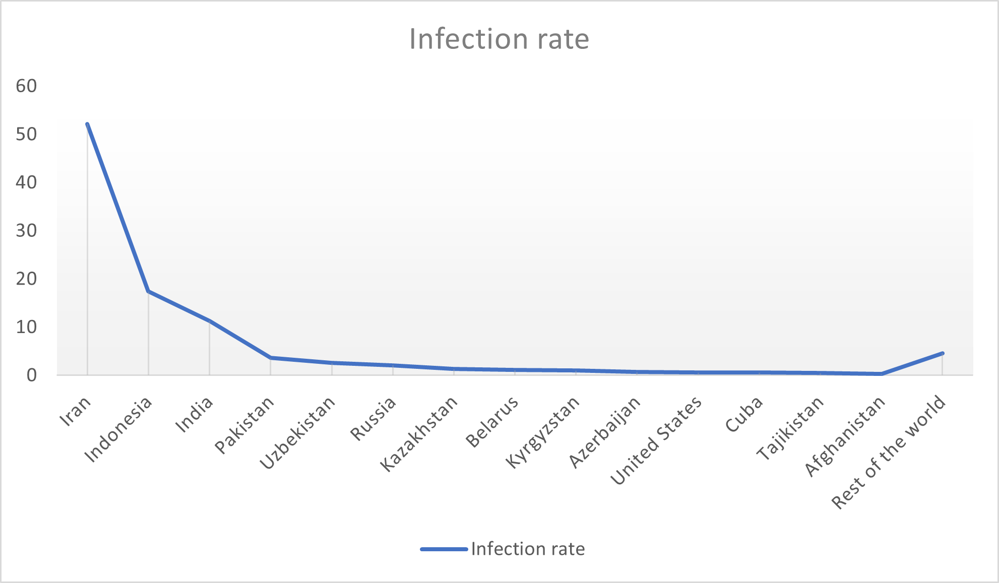
A high volume of infection and spread of a malware in a region can indicate that the region is the primary target of the attack. However, there may also be other potential targets, and the reckless nature of the infection mechanism may hint at the specifics of the targeting. Although the highest detection and infection of Stuxnet was reported in Iran, it cannot be conclusively stated that Iran was the only target of this attack. More precisely, Iran was the primary target, and in the next phase, damaging nuclear sites in other Middle Eastern countries was also considered. Additionally, the widespread and self-replicating nature of the malware led to more systems being infected.
Fundamental Concepts of SCADA Systems
Supervisory Control and Data Acquisition (SCADA) refers to large-scale control and measurement systems. Typically, SCADA refers to a central system that monitors and oversees a site or extensive system across wide distances (up to several kilometers).
In a SCADA system, the control room can issue necessary commands based on the obtained data. Additionally, this data is stored in a data logging system or database management system, which often includes graphing and analysis capabilities.
SCADA systems are used to monitor or control processes such as chemical processing, transportation, urban water supply systems, electricity generation and distribution control, and in oil and gas pipelines, as well as other large and distributed processes.
In summary, all systems used in nuclear power plants, air defense control networks, power plants, water, gas, oil, transportation, banks, and communication infrastructure systems, as well as systems controlling the status and physical functions of other systems, are called critical infrastructure systems.
In earlier decades, these systems were physically isolated from others and controlled mechanically. Today, however, all of them and their controlling infrastructure can be connected to the internet, which introduces a significant security risk (on a national level). But why can connecting these types of systems to a network be dangerous? Unfortunately, when examining the security mechanisms designed to protect the information in industrial systems, we find that, unlike computer systems with numerous defined and implemented security protocols, industrial systems have minimal security measures in place.
The most important part of a critical infrastructure system is its network control system. The network control system collects real-time information about the system’s status and communicates the system’s status on a map to the operator through an understandable graphical interface.
Critical infrastructure systems can include large systems such as a Smart Grid Network or smaller units such as a Phasor Measurement Unit (PMU) in a power transmission network, a PLC controlling steam or refrigeration in a power plant, or a remote measurement unit/sensor in a small manufacturing plant.
In this paper, we will explore how a critical system can change from one network to another. Another critical part of vital systems is the control system, which is referred to as the Industrial Control System (ICS).
SCADA System Components
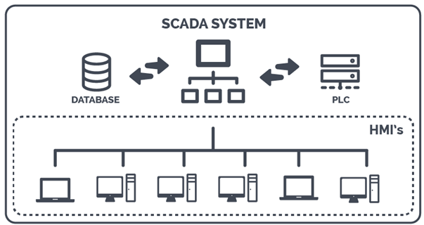
If you study the concept of systems, you will realize that the foundation of the world consists of systems. Each system has an input, processes it, and produces an output. Every system is composed of various components that interact with each other. In the case of SCADA systems, we are dealing with a system composed of several components, which are interconnected. A SCADA system consists of the following components:
Sensors and Actuators: Sensors measure physical parameters such as pressure, temperature, flow rate, levels, and proximity. These signals are then converted to binary form to make them understandable to computers. Common industrial sensors include resistive detectors (RTUs), thermocouples, etc.
Human-Machine Interface (HMI): The HMI acts as a bridge between the operator and the machine, allowing the operator to easily view all system data (both new and old) in the form of schematics, KPI dashboards, and reports. In other words, the operator can easily view system information and interact with and control the system. HMIs provide warnings to inform the operator in case of anomalies or security breaches in the SCADA system.
Historian: A historian is an optimized database used to store large volumes of industrial time-series data. It collects data from field devices such as sensors and continuously updates parameters and events. The speed of data collection and retrieval in historians is higher than in conventional databases like MySQL.
- Time Series: A time series refers to a sequence of observations arranged in chronological order. Simply put, it refers to the continuous observation of a variable over time, such as the temperature of a boiler, where the temperature is recorded in a database in chronological order.
Remote Terminal Units (RTUs): RTUs are field controllers based on microprocessors that communicate directly with sensors and actuators. They collect telemetry data from sensors and then transmit it to the central SCADA server via communication networks. RTUs also receive and execute control commands from the central ICS system.
Programmable Logic Controllers (PLCs): PLCs are industrial computers primarily responsible for controlling and automating industrial processes. PLCs process input signals from field devices such as sensors and send appropriate output signals to control actuators such as valves, motors, and switches. For example, a PLC may receive the temperature of a boiler as input and decide to perform a specific action when the temperature reaches 400°C.
Master Terminal Unit (MTU): The MTU serves as the central server for the SCADA system, containing both hardware and software layers. MTUs collect telemetry data from field devices, perform necessary processing, and store the data. They also display information to the operator through the HMI and can send control commands to field devices via PLCs and RTUs.
Data Communication Infrastructure: This component connects different devices in a SCADA system. In the past, before the advent of Fieldbus controllers, devices and controllers were connected using RS-232 serial communication, which had the limitation that only two devices could communicate. Today, with Fieldbus connections, multiple devices (field devices) can connect to a controller (PLC).
Deep Dive into the Purdue Model
The Purdue Model, also known as the Purdue Enterprise Reference Architecture (PERA), is a reference model designed for data flows in fully automated factories. It serves as a standard for constructing the network architecture of Industrial Control Systems (ICS) that also supports OT security. This model separates network layers, creating a hierarchical flow of data between each section. In other words, it separates physical processes, sensors, supervisory controls, operations, and logistics. The Purdue Model acts as a key framework for segmenting ICS networks to protect Operational Technologies (OT) from malware and other attacks.
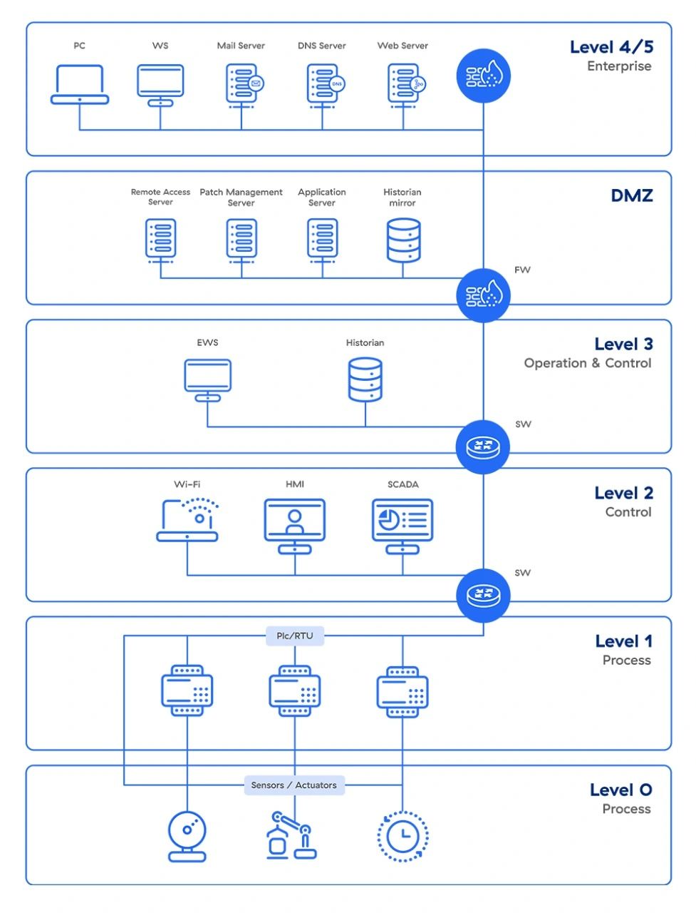
As seen, this model has six components that include both Information Technology (IT) and OT systems. When these components are properly implemented, they create an air gap between ICS/OT and IT systems, effectively isolating them. The benefit of this separation is that organizations can easily control access without disrupting the performance of other systems, ensuring the proper structure and architecture of ICS systems are maintained.
In the Purdue Model, OT systems, which include operational processes, are located at the lower levels, while IT systems, related to information technology, are situated at higher levels. Between these two levels, there is a segment known as the Demilitarized Zone (DMZ), whose primary function is to create a security layer to protect communications between IT and OT networks, facilitating data exchange between the two levels.
Now, let’s examine each level of this model from top to bottom.
Level 4/5 (Organizational): This level encompasses IT networks, including services such as web services, email systems (email servers), and Enterprise Resource Planning (ERP) systems. The ERP section manages production systems and executes processes like factory production planning, material usage, and transportation. It’s important to note that any disruption at this level could result in significant economic losses.
Level 3.5 (DMZ): This section serves as a layer between IT and OT and includes security systems like firewalls and proxies. The goal of this layer is to prevent lateral movement of attackers between IT and OT networks. Increasing automation needs have led to the creation of bi-directional data flows between OT and IT layers. It’s also worth mentioning that if an organization’s network architecture is flat, it can increase the cybersecurity risks. At this level, OT-based devices with Linux and Windows operating systems are present, and services like WSUS (Windows Server Update Services) can be used for patch management of OT Windows devices.
Level 3 (Production Operations System Area): This area contains custom OT devices that manage the flow of factory production. This section includes:
- Manufacturing Operations Management (MOM): This system manages the operations (processes) of production.
- Manufacturing Execution Systems (MES): This system collects real-time data, resulting in product optimization.
- Historian Data: In addition to storing process data over time, it performs contextual analysis. For example, modern systems can compare and analyze temperature or steam data with similar data from a specific time series or under particular conditions to identify potential problems.
Level 2 (Control Systems Area): This region includes systems designed for monitoring, controlling, and supervising physical processes. Systems in this area include Distributed Control Systems (DCS), SCADA (Supervisory Control and Data Acquisition) software, and Human-Machine Interfaces (HMI).
Level 1 (Intelligent Devices Area): This section includes devices such as PLCs (Programmable Logic Controllers) and RTUs (Remote Terminal Units) that send commands to devices at level 0.
Level 0 (Physical Process Area): This section includes physical processes like sensors (e.g., temperature and pressure sensors). Modern sensors often communicate through cellular networks and connect with monitoring software deployed in cloud environments.
Features of Site SCADA and Regional SCADA
Manufacturing industries often use the term Site SCADA for their supervisory systems, while Regional SCADA refers to supervisory and control systems used to manage critical infrastructure over a wide geographical area. To summarize the distinction between Site SCADA and Regional SCADA, it primarily comes down to geographical scale. Site SCADA is typically used for monitoring and controlling a specific site or a small geographical area.
Now, let’s explore the features and standards associated with Site SCADA and Regional SCADA:
- SCADA systems are based on TCP/IP technology.
- SCADA systems usually use standard protocols, meaning they typically use protocols supported by all vendors.
- Both systems are located at Level 3 of the Purdue model.
DCS Overview
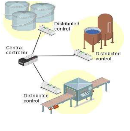
Distributed Control Systems (DCS) became popular in 1975 and remain one of the most widely used systems to this day. The popularity of these systems can be attributed to increased accessibility, advances in computers, and the widespread use of microprocessors in process control. It is worth noting that DCS includes distributed digital controllers, which, due to their functional or geographical distribution, allow complex processes to be efficiently controlled and managed.
Distributed control systems typically use proprietary controllers, protocols, and connections. The DCS units are placed at Level 1 of the Purdue model and are directly connected to physical equipment such as switches, pumps, etc., located at Level 0 of the Purdue model. DCS units are also connected to HMIs, which are located at Level 2 of the Purdue model.
DCS are used in complex processes that involve multiple operators. As mentioned earlier, distributed control systems are essentially a type of proprietary system, often used in continuous and large-scale production processes such as oil refining, electricity generation, fertilizer production, pharmaceuticals, cement manufacturing, and more.
DCS systems connect to sensors and actuators to control material flow in a factory. Modern DCS units also support neural networks and fuzzy logic applications.
Industrial Control Systems (ICS)
Industrial Control Systems (ICS) typically include various types of control systems, such as Supervisory Control and Data Acquisition (SCADA) systems, Distributed Control Systems (DCS), and Programmable Logic Controllers (PLC). ICS are widely used in nuclear power plants, power plants, electricity distribution networks, oil and gas systems, as well as in transportation, defense industries, waste collection, and even automotive manufacturing. ICS are systems that do not require a human operator to perform their tasks. In some types of ICS, the control network is physically isolated, forcing the system to communicate with other control stations via a network.
There are two key components in Industrial Control Systems (ICS) whose functions are interrelated: SCADA systems and Programmable Logic Controllers (PLC). SCADA systems are designed to provide real-time information to a human operator and can offer information on the current state of physical processes, as well as the ability to make changes to the process remotely. SCADA systems are widely distributed in industry today and are geographically separated from centralized data collection systems.
In a Distributed Control System (DCS), SCADA systems usually control multiple interactive systems, each responsible for a local process. DCS are widely used in industries based on physical processes. On the other hand, a PLC is an embedded computer-based system that can control industrial equipment or processes and can also organize the execution flow of processes. PLC systems are commonly used along with SCADA systems to execute operator-supervised operations.
The first ICS systems in 1977 could not connect to an external network; however, they had the ability to connect to a local network with a closed control environment and proprietary protocols. Modern ICS, however, fully support the TCP/IP protocol stack, run on real-time operating systems, and can connect to the global internet.
Due to this, we will face many security issues in the future for ICS. Industrial Control Systems (ICS) are a critical part of vital infrastructure, so the emergence of a security issue in ICS can directly impact the infrastructure systems.